PIC-IO development board
Introduction :
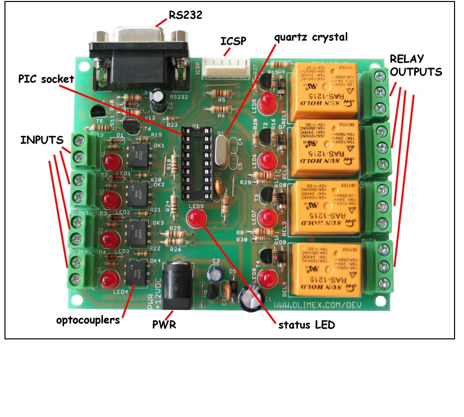
PIC-IO board was designed as simple platform which to allow control of appliances and devices with PIC, the idea was to build something like tiny PLC controller which is possible to program in C or assembler instead of the weird PLC relay language. Let’s see what we have on board: Four High voltage/ High Current relays – with NO-NC-COM contacts available on terminal block. The relay switching current is rated: 15A/125VAC, 10A/250VAC, 15A/24VDC. Note that these relays are good for switching resistive loads, but if you have to commutate inductive loads the relays will wear off quickly due to the sparking when disconnect the inductive loads (like motors). Each relay have status LED associated with it so you can easy see which relay is in ON and which in OFF state. O1 is connected to RA3 CMP1 and PIC CCP module can be used to generate ON/OFF pulses. O2-O3-O4 are connected to RA2-RA1-RA0.
 FEATURES
- ICSP/ICD connector for programming with debugging with PICKIT2 /PICKIT3
- Power plug-in jack for +12VDC power supply
- Voltage regulator +5V, 7805 and filtering capacitor
- 4 optocoupler isolated inputs with screw terminals
- Input status LEDs
- 4 relay outputs with 7A/250VAC contacts with screw terminals
- Output status LEDs
- Status LED connected to RB5
- Quartz crystal oscillator circuit 20Mhz
- DIL18 microcontroller socket
- RS232 DB9 female connector
- RS232 interface circuit with Tx, Rx signals
Package Content
1x Tested Board with Chip 16fxxx
- SOFTWARE: DEMO1: PIC16F628-I/P CONTROL SOFTWARE
- This is demo code, which allow control of the PIC-IO inputs/outputs via PC with Hyper terminal.
- Connect PIC-IO RS232 with cable to your PC and run
- Hyper terminal with these settings: 9600,8,N,1,NONE.
- When you apply power this will be seen on the Hyper terminal window:
- To read the inputs in binary format type “r”, PIC-IO will respond with something like: %0000
- if all inputs are 0 or %1111 if all inputs are 1 (i.e. +5V is applied) the inputs are with right less significant bit i.e.
- the order is: I4 I3 I2 I1 To read the inputs in HEX format type “R”, PIC-IO will respond with something like: $0
- if all inputs are 0 or $F if all inputs are 1 To change the outputs type “w0101”, this will switch on relay 1 and relay 3 and will switch off relay 2 and relay 4.
- If you want to use HEX value you can write “W5” for instance which will switch on relay 4 and relay 1 and will switch off relay 2 and relay 3.
- Any other commands will not be recognized and PIC-IO will respond with “ERR”
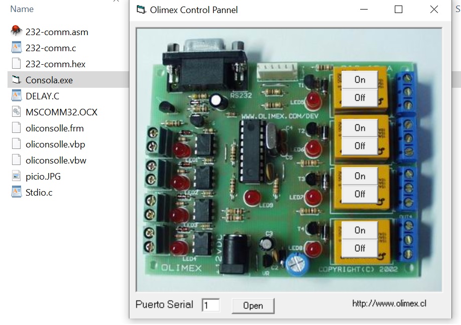
DEMO SOFTWARE TO CONTROL RELAY -

- CONNECT uisng usb to uart converter
- select com port No > check in device manger
- open the software Click on relay On / OFF to trigger relay
- Download Software
PIC-IO BOARD - 4I/4O
- Product Code: PIC-IO dev board
- Availability: In Stock
-
Rs950.00
Related Products
USB TO UART
USB to UART Converter – CH340 Chipset (RS232 + TTL Output)Overview: This USB to UART Converter is..
Rs300.00
USB to RS485 Converter
USB to RS-485 Converter The USB to RS485 Converter Adapter Module provides an easy-to-use RS485 I..
Rs800.00
Tags: PIC-IO BOARD - 4I/4O


